KDDI and Kyocera leveraged their wireless relay technology to expand street-level connectivity from 33% to 99% within a 600-square-meter urban area.
Recently, KDDI and Kyocera demonstrated a new wireless relay technology that significantly expanded millimeter-wave (28 GHz) coverage in urban environments. With the successful test, the companies believe their new solution could have major implications for expanding 5G deployment.
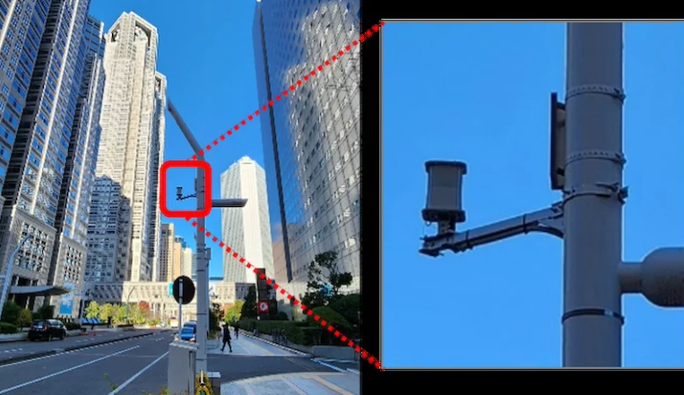
Repeaters installed in Nishi-Shinjuku area.
KDDI and Kyocera's Wireless Relay Tech
The KDDI and Kyocera's wireless relay technology employs miniaturized repeaters that autonomously form a mesh network by dynamically adjusting their transmission and reception roles based on real-time environmental conditions. Where conventional relay systems require predefined donor and service antenna configurations, these repeaters optimize signal paths by continuously recalculating relay routes to minimize interference and maximize coverage.
Each unit measures 216 mm x 216 mm x 246 mm and weighs 4.9 kg, which the companies claim reduces installation complexity by 70% compared to traditional base stations. The compact design also allows deployment on existing urban infrastructure, such as streetlights, without requiring extensive backhaul connections.
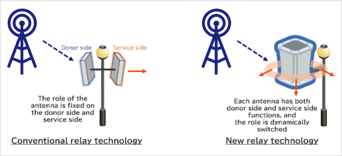
Conventional versus new relay technology.
Initial field testing in Tokyo's Nishi-Shinjuku district demonstrated a threefold increase in coverage by expanding street-level connectivity from 33% to 99% within a 600-square-meter area. This testing involved 22 repeaters installed on Tokyo Metropolitan Government and Shinjuku Ward assets as part of the "Connected Tokyo" initiative. The relay technology successfully maintained high-frequency connectivity, even in areas where base stations previously struggled to provide stable service. The repeaters mitigated coverage gaps by detecting and rerouting signals around obstructions, such as buildings and large vehicles.
The Circuitry of a Wireless Repeater
A wireless repeater functions as an intermediary device that receives, amplifies, and retransmits signals to extend wireless coverage. Generally, its circuit architecture consists of several components: a low-noise amplifier (LNA), a mixer, a local oscillator, a power amplifier (PA), and a duplexer or circulator to manage signal routing. Together, these components enable the repeater to capture weak signals, amplify them with minimal noise, and retransmit them at higher power to extend coverage without degrading signal integrity.
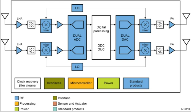
Internal block diagram of an NXP wireless repeater.
First, the repeater’s antenna captures the incoming millimeter-wave signal, which is typically weak due to high propagation losses. The LNA is the first active stage in the signal path, amplifying the received signal while minimizing additional noise. Once amplified, the signal is downconverted using a mixer and local oscillator (LO). This conversion shifts the high-frequency, mm-wave signal to an intermediate frequency (IF) and allows the repeater’s internal circuitry to process it more efficiently. Some advanced repeaters use direct digital conversion to bypass the IF stage and reduce power consumption and latency.
The downconverted signal is then re-amplified using a power amplifier (PA) before retransmission. The PA is optimized for high linearity and efficiency so that the output signal maintains its original characteristics while operating within regulatory power limits. Modern repeaters often incorporate digital signal processors (DSPs) and beamforming algorithms to dynamically adjust transmission angles and optimize relay paths.
Finally, the repeater upconverts the signal back to its original frequency and transmits it via a high-gain antenna.
From Test to Urban Implementation
KDDI and Kyocera plan to commercialize the technology by the end of 2025, with sights set on high-density locations such as transit hubs, stadiums, and urban centers.